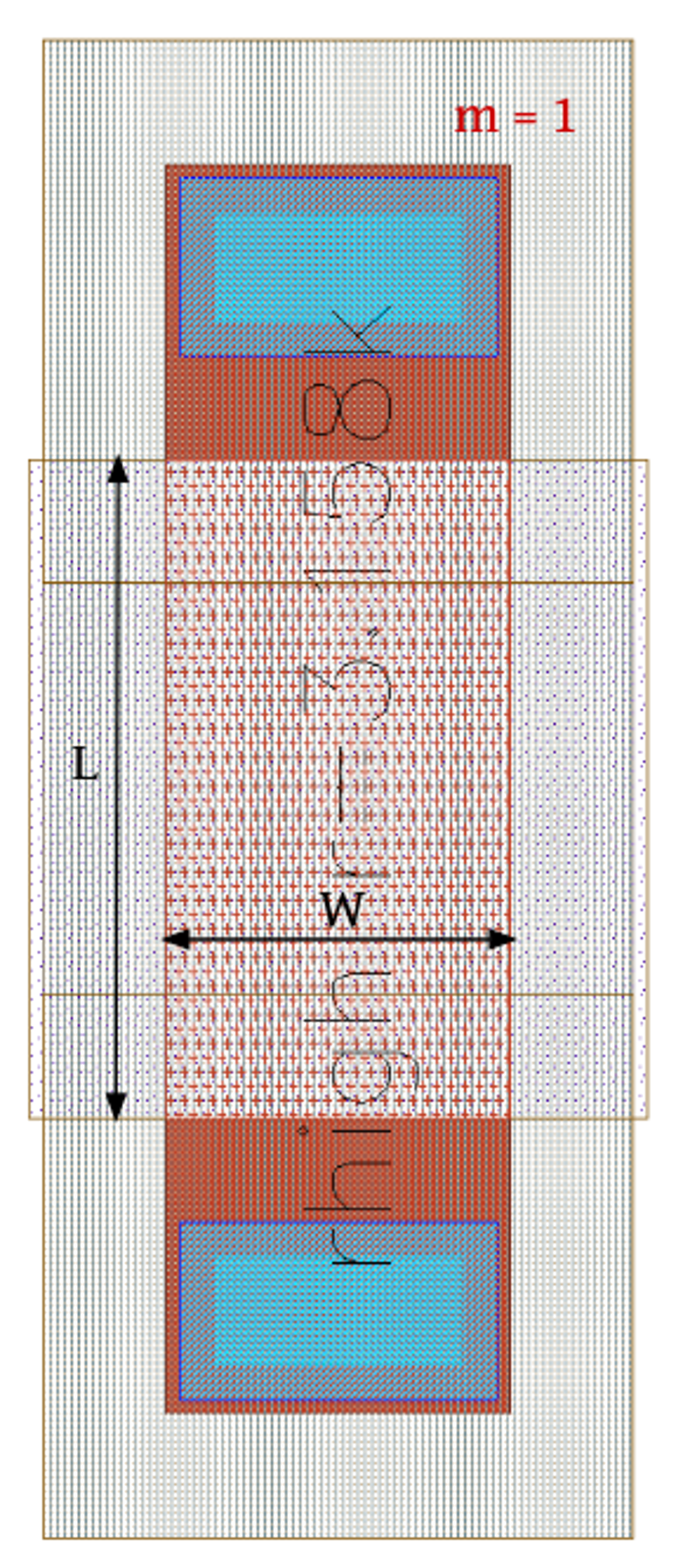
2.1 Resistor
A resistor is a two-terminal passive electronic component that resists the flow of electric current. Simply put, it limits how much current can pass through a circuit. It’s one of the fundamental building blocks in electronics.
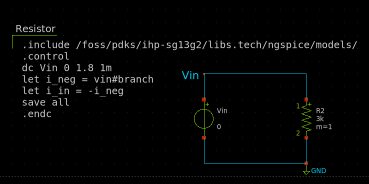
The following circuit shows a resistor connected to a voltage source. The xschem simulation file can be found here.
Characteristics
Resistor behavior is governed by Ohm’s Law, which states:
\[V=IR\]
Where:
- \(V\) is the voltage across the resistor,
- \(I\) is the current through the resistor,
- \(R\) is the resistance in ohms (\(Ω\)).
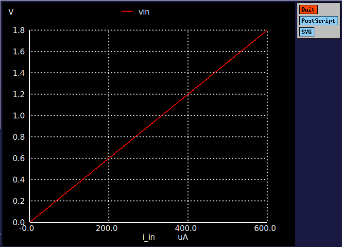
Characteristics curve
The ideal resistor has a linear V-I characteristic, meaning voltage and current are directly proportional. When plotted on a graph:
Resistance
Resistance (\(R\)) can be modeled by the mathematical equation,
\[R = \frac{\rho A}{L}\]where:
- \(R\) is the resistance in ohms (Ω),
- \(\rho\) is the resistivity of the material in ohm-meters (Ω·m),
- \(L\) is the length of the conductor in meters (m),
- \(A\) is the cross-sectional area of the conductor in square meters (m²).
In manufacturing process this equation is the fundamental model to make a resistor.
IC level Implimentation
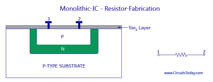
At the integrated circuit (IC) level, resistors are implemented directly on the silicon chip using materials such as poly-silicon or diffused regions within the silicon wafer. These resistive elements are carefully structured as thin, straight lines or serpentine (zig-zag) shapes to control the resistance value while fitting into a compact area. The fabrication of these resistors is done using standard CMOS (Complementary Metal-Oxide-Semiconductor) processes, which often overlap with the steps used for creating transistors.
The sheet Resistance
Sheet resistance is defined by resistance per squre sheet in IC designing.
since,
\[R=\frac{\rho l}{A}\]making the squre shape \(L=W\) will result with, sheet resistance;
\[R_s=\frac{\rho}{D}\]where \(D\) is the depth of the resistor. so the sheet resistance will independent of the size of the squre.
then any resistance can be implemented as,
\[R=R_s.\frac{L}{W}\]